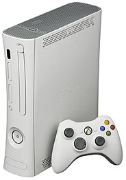
ExBox 360 : Return of the Exiled King

Right, so the XBox 360…
I was going to do this thing about the background of the console, why it’s the king of its age, how I missed out on that era of console gaming, and my rationalizations for deciding to get my hands on the actual console long after its reign had ended, but nobody wants to slog through that to get to the good stuff.
Okay fine, the bullet points then:
I want to experience some of what happened while I was otherwise engaged working my ass off to pay the bills, but even though this era of gaming has been left behind commercially, collectors are continuing to ensure the costs of entry are damn near the original retail levels. This is a free-time hobby, and I’m not overflowing with cash (I had to hock the jet to afford some Taco Bell). Also, second and third-hand title sales are such a crapshoot, with media that has near-invisible but game-breaking damage, and outright copy scams. It’s like buying a VHS tape from the guy at the union plant, only to find that “original “pristine” copy of Transformers The Movie has been dubbed over with porn. Ugh.
Emulation is not really there (yet). A great majority of the available games don’t work the way they should (if at all). I want to be able to be a virtual gaming butterfly, checking out titles without concern for whether I’ll actually be able to, you know, play them..
I have an XBox One S, which claims to have at least some backward compatibility with 360 discs, but personal experience shows that it doesn’t seem to be able to run most of the 360 titles named on the official compatibility list (which “somehow” changed from including the One S, to suddenly only mentioning the later Series models). Any better-performing third party emulation solution on that console is also painting a target on oneself for XBox Live account ban, too. I’m sure they want to reserve the right to “remaster” (port and release as-is) legacy titles for an additional profit injection. Lots of 360 titles are available for sale on the Live store, as “classic retro” games. :/
There are enough unique major titles to justify wanting to expend the effort to play them on the hardware they were originally designed for, rather than second-rate ports.
Okay that’s out of the way, screw it. Let’s mod an XBox 360 console!
Modding it to play disc backups helps keep a physical media collection in good shape, and eliminates the hassle of swapping discs. I mean, they came with wireless controllers, but then set things up so we still have to manually swap the media? This isn’t the Atari age: we don’t sit on the floor with the console directly in front of the TV anymore.
Look, if you’re reading this, you’re probably already well aware of where we’re going with this. Obviously I’m going to recommend you legitimately own the titles you want to back up for play on this system. There are plenty of sources for content online, but that’s your choice to make. If you’re planning to follow this through to its conclusion, then your fingers aren’t broken and you’re old enough to read, so figure out how to Google things. 😉
The Pitch
Hold onto your butts…
This is not a casual sort of process. This is going to get fairly technical, so if you’re not experienced working with electronics –and I mean the soldering and everything– then you don’t want to get into this. You need to be able to understand some of the terminology and lingo being used here, or you’re going to get lost and Very Bad Things(tm) will result for your poor console. Make sure you are clear on what is being done, any why, before you try doing it yourself! At the very least, skim through this post and maybe watch the linked video below to get a sense for what’s going to be done, before diving in headfirst.
Where do we start? First, look through the various methods and settle on one that appeals the most. I will be using a method known as the Reset Glitch Hack (v3) to replace the bootloader and dash, as it works reliably, doesn’t require buying and installing a special chip, and is well-documented.
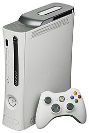
So which console to use? There are a few models, with variations within each to complicate things further. Thankfully, choosing a hack method also helps limit the choices a bit. I’m going with the “S” (Slim) model, as it has the best compatibility for the route I’m choosing. The “E” model looks appealing for its simplistic design, but it is probably the most difficult of the line to mod (the most common motherboard version codenamed “Winchester” in the E line is completely un-moddable).
 |  | 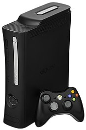 | 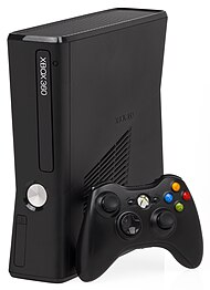 | 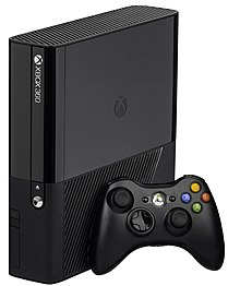 |
| Xbox 360 Arcade | Xbox 360 Pro | Xbox 360 Elite | Xbox 360 S | Xbox 360 E |
The Script
Full disclosure
I am totally following somebody else’s existing walkthrough on how to do this. I will not be presenting the full process here myself when others have done such a superb job of it already, but I am attempting to share the reasoning behind specific decisions, and some of the issues and pitfalls I encountered that might not have been mentioned or called out by others along the way.
The original video for the process I followed is here, if you’d like to get a sense for what’s involved. I highly recommend a video “dry run”, so you can at least be familiar with what specific steps should actually look like, first. This video shows the mod being performed on a “S” model, Trinity board (most easily recognized by the power draw of 10A shown on the label).
There is a little debate about which is better for this process, between the Trinity and Corona motherboard versions. However, if you’ve not done this before, you will benefit from working on a Trinity, as its design makes the process a bit easier with more accessible pads. Trinity boards do run a bit hotter, true, but they also do not require an additional adapter sled to perform the mod, and seem to have a lower rate of failure as well, if forum post history (Reddit, et al) are to be taken as gospel.
The Players
Donor Console


XBox 360 “S”, purchased from eBay. The board was identified as a Trinity before purchase by verifying the power draw value for the 12v rail on the back label. If you have a board in-hand already, you can do a visual match with this site to identify it.
I very much don’t like buying things off eBay any more than I have to, because it can be such a swamp of scams and theft. However, it is usually the best place to find a deal for something like this, so it’s a matter of being patient and thorough, and of course doing lots of comparisons, because there are plenty of people offloading these things right now! If you’re in the market, you can find them refurbished and verified from stores, but the nice deals are the individuals just looking to recover some entertainment center space.
Relying on yard sales, garage sales or estate sales is a frustrating lesson in patience and effort; you have no idea when you might find what you’re looking for. However, it’s possible you’re here because you already scored an awesome sale find, in which case: congratulations!
Any pawn shop or (really any secondhand retailer) is going to be out to make as much money as they can, making the prospects more expensive than it has to be. The exception to that statement would be charity shops like Goodwill or Salvation Army. That said, there is an argument to be made for the value of something that has already been tested and verified to be fully functional before you, you know, completely tear it apart.
In the end, the final call is yours. It all comes down to how much you’re willing to spend to get this show on the road, in the first place.
Tools and Supplies
A couple of the components we need are unique to this endeavor (you can click the images for links to purchase sources):
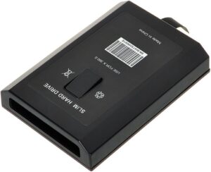
Drive caddy
The console I purchased doesn’t have one, and of course the hard drive to go in it. You do NOT need a SSD drive; an old-school spinning disk will be more than sufficient if you have one laying around (the bus on the console can’t take advantage of the enhanced capabilities of SSDs, so all you’ll get out of using one is possibly better longevity). I’m using a 1TB spinning disk I had left over from a XBox One S drive upgrade, which makes this older version much faster anyway. The SSD is used for dropping software to the console when it’s up and running.
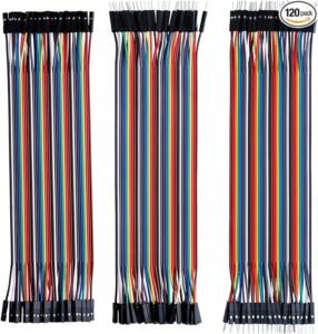
Breadboard jumper wires
Makes connecting our things easier to do
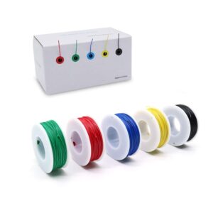
30 AWG hookup wire
Trust me, you want this very very thin. It doesn’t even have to be what I used, just so long as it’s insulated and THIIIIN.
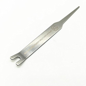
X-clamp removal tool
This will help with not only opening the initial case, but is also needed to remove the CPU cooler safely. You don’t have to have this thing, but it’s cheap, and makes a really tricky part of the process much easier.
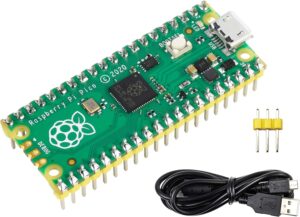
Raspberry Pi Pico
Our digital lockpick, letting us jack into the console’s mainboard to do some Indiana Jones shit on the firmware
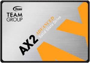
1TB or 2TB SSD
You don’t have to run out and get a new SSD, but the capacity makes it easier to load up the XBox after things are completed and you’re ready to start building your library. Otherwise you’re going to be going back and forth quite a bit with that bitty little thumb drive you had laying around instead. 🙂

(1) 3k-10k Resistor
If you’ve been doing any electronics stuff, you should have something compatible laying around. If not, ask your parents. Guaranteed dad has something buried in a small parts organizer somewhere around the workbench!

Thermal compound
This is a must. You’ll be removing the heat sink assembly during this work; you do NOT want to re-use the existing compound, especially if it’s factory stock. Many of those Red Ring of Death issues these consoles suffered from were caused by bad or insufficient heat compound under the heat sink. You could actually fix a problem in the making for your console while completing this mod! Arctic Silver has always been my go-to, but once in a while I only have the standard gray goop stuff laying around when I need it. Either should work fine.
A couple of items that may help you out a bit later:
- Desktop magnifying glass OR
- Phone or webcam tripod (whichever you may have that provides the best zoom capabilities for super closeup (macro) shots/video
After that, it’s the standard list of electronics stuff (not shown because you’re supposed to be experienced with this kind of stuff, so you should already have most of it, right?):

Soldering iron, finest tip you have (and all the related supplies like flux, solder, etc)
Heat shrink tubing
Torx driver set (or at least T-8 and T-10 size torx bits!)
Kapton tape (optional but highly recommended)
99% IPA (Isopropyl Alcohol)
QTips (cotton swabs/buds)
So one change I made from the recommendations in the video was to use straight jumper wires instead of a breadboard for the RPi Pico hookups. Why?
- Depending on the breadboard you have available, connections may be unreliable, causing confusion and hassles during the NAND backup and programming phase.
- You’re going to need to be able to flip the the mainboard around while the jumpers are soldered to it. If you have extra weight hanging from them, you run the risk of ripping pads off, which is very bad. If you arrange the wires right, you can very easily disconnect and reconnect the Pico as-needed during the different phases with very little trouble. Not quite so simple with a breadboard assembly (again, only a real issue if you got cursed with sub-par cheap Chinese breadboards).
Software
Now, it gets interesting. It also gets more technical (which is interesting), so you might start to feel a little dizzy with all the jargon. That’s okay, just look things over, and if they feel like they still make sense in what’s being done here, you’ll be fine.
So let’s go get the software we’ll need. Organize it into a nice folder and rename the files if it helps keep things straight.
RPi Pico firmware (PicoFlasher)
MANDATORY (can’t mod the board if you can’t read/write the firmware!)
ABOUT: https://github.com/X360Tools/PicoFlasher
DOWNLOAD: https://github.com/X360Tools/PicoFlasher/releases/
You will need this for the Pico to do its thing, once it’s connected to the console’s motherboard, later in the process. The firmware sets up the Pico to be able to communicate with the motherboard and NAND when it’s connected and powered. Current version at the time of this writing is 3.0, released Feb 23, 2022.

J-Runner
MANDATORY (for this version of the process; there are other ways and other tools too)
DOWNLOAD: https://github.com/Octal450/J-Runner-with-Extras
JRunner is the utility that will allow you to confirm the connection, backup the stock firmware, build customized firmware for the hack, and install it to the mainboard.

XEXMenu
MANDATORY
ABOUT: https://consolemods.org/wiki/Xbox_360:XeXmenu
DOWNLOAD: https://digiex.net/threads/xexmenu-1-1-download-xex-menu-iso-live-and-xex-file-manager-for-xbox-360.11096/
This is low-level file manager that will let you perform the first initial utility operations on the XBox after the mod is installed, like installing DashLaunch. You want the Live/XEX version download.

DashLaunch
MANDATORY
ABOUT: https://consolemods.org/wiki/Xbox_360:DashLaunch
DOWNLOAD:https://www.mediafire.com/file/39z8ntp7j9dky6x/dash_launch_v3.21.zip/file
This is the custom dashboard launcher. You need a custom dash to be able to access additional features that weren’t possible with the stock Microsoft interface. For example, it’d be nice to be able to actually copy and run your game discs entirely from the internal hard drive, wouldn’t it? Wouldn’t you like to be able to play your games without having to get up and swap the damned discs around? I mean, wasn’t the part of the point of having wireless game controllers to help unchain us from having to be near the console all the time? This utility will let you be free from touching the discs (after you copy them over).

Aurora
OPTIONAL (but recommended)
ABOUT: https://consolemods.org/wiki/Xbox_360:Aurora
DOWNLOAD: http://phoenix.xboxunity.net/#/news
This is the “dress” on the dash. It gives you a pretty interface to work with, and does much the same job as the interface you got with the stock XBox 360 experience, but with more capabilities.

Opening Night

The stage is set, the star is prepped and ready for surgery, and the audience waits with bated breath- wait what?
Yeah, I said it: surgery. We gotta go pretty much Johnny 5 levels of disassemble to do what comes next, but if you have soldering experience, a steady hand and a cellphone with a stand, you’ll survive this just fine.
So let’s do this. Also, to be perfectly candid, you can actually do this whole process just following the video up there. That’s how I did it; I’m just offering up my perspective on minor little gotchas I discovered along the way.
We need to get access to the console’s mainboard, front and back. This means we’ve got to remove it from the console altogether, which in this case does mean we’re going to have to tear the console down to its base components before we can access the good bits.
iFixit has a great walkthrough on how to open and remove the shell.
End Trims
Remove vent covers
Use a spudger or the x-bracket tool pointy end to gently pry up the vent cover pieces on both sides.
Remove the hard drive from its slot and set aside


Release end trim clips
You will now remove the actual end trims by inserting the X-clamp tool pointy end or a spudger, and prying open the clips
You will insert the blade pointing inward and just slightly toward the case top or bottom, whichever side you’re currently closest to. Your goal is to feel your tool getting under the clip loop, then gently pry it just a little bit away from the nearest panel. So if you’re working the top row of clips, you should be going into one of the holes almost level, but aiming slightly upward, to get your tool underneath the lip of the loop, then bend it just a little bit downward as you pull gently on the trim piece toward you. It should come away at just that spot where the clip is.


Remove end trims
Maintain the gentle pulling pressure on the trim plate as you go to the next clip in the row. Work your way around, making sure to keep gently outward pressure on the trim so it doesn’t re-secure itself on clips you just released.
When you’ve reached the last clip, the whole trim should just easy pull away.
Put it somewhere safe and out of the way for now, and repeat the process with the other end.
Right/Bottom Shell
Separate the shell halves
As you look into the right end of the console, you’ll see the wifi card, and at the very back, one of the clips that’s holding the shell halves together. Use a spudger to release this one, then from here you’ll want to start putting pressure on the halves along the back seam to move them apart as you release other clips along the line.

Remove the bottom cover
You need to remember that only the bottom half of the shell will come away simply by unclipping things. The top half (the half that faces upward if you lay the console flat so that “XBOX 360” on the DVD drive is horizontal and right-side-up) is secured with some screws that go through the whole unit. We’ll get to those, just get that bottom half off carefully. Have some patience and don’t use a ton of force. It’ll come away once you get the feel for where it’s secured and how to release it.
Don’t forget you’ll need to cut the warranty sticker that crosses the seam, unless of course you or someone else has been in there before. Naturally, the only people who care about that sticker being intact at this point are collectors looking for a pristine, untouched model. Microsoft certainly isn’t going to offer any service on this thing by now! 😀

Face plate


Remove the touch controller/front panel light assembly
When the bottom half is free, the next piece to come off will be the front faceplate. It should be nearly hanging free on its own by now, but handle it gingerly. It’s still attached by a sensitive component!
DO NOT SIMPLY YANK IT OFF. The buttons on the plate are connected to a board secured to the chassis. You will need to release this ribbon cable first.
First, gently pry up the blue plastic retaining ring from around the cable connector. This is like a pull tab that wraps around the connector body to hold the ribbon cable firmly in place.
Gently push the retaining lock up from the connector body. It only moves just a couple of millimeters between locked and unlocked, and you can see the difference between the first two photos above. In the very first image, it’s still locked, then unlocked in the second one. Again, very little force is needed to do this. Trust me. Don’t ask how I can be so certain.
Now just remove the two screws holding in the light module, and pull the module straight out of its USB-like connector plug.
WiFi Card
Remove the wifi card
Now around on the side opposite from the hard drive slot, you will see the wifi card in an alcove near the back of the case. Remove the screw securing it in place, then remove the card. It’s a straight plug similar to a USB socket.

Top/Left Shell
Remove shell chassis screws
Now it’s time for the top (or right) case half. From the bottom (left) side, remove these screws securing the cover to the chassis.


Remove final shell piece
Flip back over again, and lift the cover away gently.
Lift off the RF and grounding shield underneath, finally exposing the motherboard and various other components within.
The shield may or may not remain attached to the case cover, especially if somebody has been in here before. If it does not come away with the cover, it is only friction-fit onto the chassis and can be pried up off the internal metal shell easily.
Optical Drive
Remove optical drive
Now, disconnect the white power connector, followed by the red SATA cable from the back of the optical drive.
Lift the optical drive out of the chassis.

Hard Drive Bracket and Fan/Duct
Release drive tray base screw
Now, flip over the chassis and remove the screw from the hole labeled “G”. This will release the drive bracket to be removed.

Remove the fan shroud
Next, flip back over and remove the fan shroud, lifting it straight up and away from the fan and heatsink assembly.


Remove the hard drive tray
Remove the screw from the back panel, next to the power connector, circled above left.
Then, remove the screw holding down the SATA/power connector on the drive tray.
Remove the drive tray from the assembly
Heat Sink and Motherboard


Remove the chassis screws for the mainboard and heatsink
From the bottom of the chassis, remove all the remaining screws. Keep the black screws at the “X” imprint aside (they’re a different size from the others, unique to the heatsink). Flip the chassis back over.
Unplug the fan power connector from the motherboard (shown here, nearest the external power plug.


Remove bracket and mainboard
Remove the optical drive grounding bracket by lifting it straight up away from the board, and out of the chassis.
Remove the motherboard by grasping the heatsink and leveraging the board out from the front edge first, bowing the metal away just a bit to relieve the tight fit from the grounding fingers around those USB ports. The board should come away; rotate it carefully out and up, finally removing it from the chassis altogether.
Behold the majesty. Gently.
Make sure you place the motherboard on a clean, protective surface. I used my silicone electronics mat. Remember that the board has very tiny, sensitive components on both sides, so be super cautious and wary in your handling of it.
Flip the board over so you’re looking at the underside. You will see a large “X” bracket toward one corner.

PAUSE HERE
If you’ve been following along with this in real-time, seriously STOP and read this section in advance. This step is simple, but do this wrong and you’ll kill your console good. This is the true purpose of that funky pickle fork-looking tool.
STEP 4a
The X bracket is not screwed down to anything; it is kept in place by its hooked ends that grip the groove cut into the heat sink posts that come through the board. When all four legs are hooked on, the tension keeps things pretty well secured.
We just need to get a couple of the legs loose to be able to remove the X bracket. To do this, we use the bracket removal tool to leverage the bracket’s hooked end up and out of the post groove to release it.
Start at the top left corner leg, as you look at the back side of the board with the big half-circle edge cut to the left. The fork end of the tool, tines facing upward, will slot directly under the bracket, fitting into the slot in the post that the bracket is clinging to. You don’t want to shove the tool all the way onto the post, but rather just far enough until it has achieved useful leverage in the slot.


STEP 4b
Now, lift the handle upward gently, and you’ll see and feel the fork leveraging on its position in the post slot to push the “hook” of the X clamp upward and off the post. Be mindful of the tool forks. Don’t let them gouge into the board itself. If they’re touching the board as you attempt to release the bracket, the tool is too far onto the post. If this helps envision it better: you only want to perform this prying motion with the tool’s fingertips engaged, not the whole fingers.
Look closely at the images on the right. Note the difference in height of the tool on the post, and the difference in how far on the post the tool has been pushed.


STEP 4c
There are some guides that will assure you this task can be done with a screwdriver, to which I say “Yeah, sure, in the roughly the same manner you can reboot your cellphone with a hammer.” You could, but the consequences of a mistake are substantially larger. Look, the tool is less than $10, and you’ve probably already spent more than that on your XBox. Don’t get cheap on me now, Dodgson. The time and risks it saves are manifold.
I mean, you could just unscrew the posts themselves, I suppose. That would simplify this part of th project, but screw you good soon afterward: good luck getting things lined up properly when it comes time to put the heatsink back on again!


STEP 4d
Release two of the arms to get enough slack to remove the bracket entirely. Flip the board back over, using one hand to hold the heat sink in place, and then gently remove the heatsink.
Depending on its age, the thermal paste underneath might be a little stiff, so try twisting the sink just a little bit to get things to come loose. Please, for the love of dog, remember there’s a fragile CPU under there. BE GENTLE, this is not a jar of grape jelly we’re opening here!
Now, with the removal of the heat sink, our teardown is completed. We’ve gone as far as necessary to perform the actual modifications, at this point. This is a good time to break out the alcohol and cotton swabs to clean the old thermal compound off the CPU and heat sink, too.


PUTTIN ON THE GLITCH: Part I – Backside Shenanigans
Get comfortable with the motherboard’s layout. Rotate it to match the biggie image below, with the heat sink area to the bottom-left, and the big round notch on the edge of the board to left side.

There are two connections to make back here, one is a bit challenging but perfectly do-able if care and patience are applied.
- The red line is a straight patch from one test point location to another. (Color isn’t important, of course. It’s just for identification.)
- We start at FT5R2: 2nd point down the left column of that slanted set near the top-right heat sink post hole. It has almost like a comic book speech bubble pointing upward from it with the actual point designations.
- We end at the right-most of two test points sitting above the label for R3R22, to the right of the heat sink area, about mid-way between top and bottom posts.
- The yellow line is the more involved one.
- It goes from a via near C5R35, just below the bottom of the slanted column of points where the red line starts, through a resistor, and then all the way down to a test point by the label FT2V1, down at bottom-right of the board, just left of the Microsoft logo.
- The actual position of the resistor on the wire doesn’t matter, but it will be more out of the way of other components if it’s attached down nearer to that bottom-right test point.
- It goes from a via near C5R35, just below the bottom of the slanted column of points where the red line starts, through a resistor, and then all the way down to a test point by the label FT2V1, down at bottom-right of the board, just left of the Microsoft logo.
Okay, now it’s time to get our magnifying gear (if available) set up. You got this part; we just want to see the details of what we’re working on more comfortably. I used my phone on an articulating desk mount arm for my case.
POST to SMC_POST Line
STEP 1
First, the red line. Strip the wire ends just a teensy bit, like maybe 3-5mm.
Solder that puppy in at the points circled in red, to the right.
A few tips:
* If you can’t get the existing solder to melt readily, add a bit of your own fresh solder as you place the wire end over the point
* Always be aware of where your iron is coming into the area. You might want to re-orient the board so you can approach a solder point without hovering over tiny sensitive components.
* I like to use the kapton tape to lay down a protective surface underneath the wire’s route (just in case it gets pinched against a solder joint or component), then secure it with another piece of tape here and there on top of the wire.

PLL_Bypass to SMC_PLL Line
STEP 1
Here is the first fiddly bit you’ll encounter. Look closely at that point right near the C5R35 label. See how it’s green? It’s actually a copper tube running through the board (called a via) that has been protected by the green solder mask coating. That solder mask is doing its job and preventing us from soldering our wire there, so we have to get rid of it WITHOUT getting rid of the copper just underneath it!
Removing solder mask at this tiny scale is not something I can presume to teach you. If you have never done it, I can only advise this is absolutely the best time to have some kind of magnification available, and that you will need to have a very VERY gentle touch, no matter what tool or method you decide to use. We just want to scratch/abrade that one little point juuuuust enough to remove the solder-proof coating, and expose the desired copper surface beneath. I chose to use an x-acto knife for this process.
You can clean up the shavings as you go with alcohol and cotton swab.
Once you have a nice clean copper surface as shown at right (again, right between the “R” and “3”), prime the via with some solder, and you’re ready to attach the wire, once it’s assembled.


STEP 2
Now, assemble the long (yellow) line. you just need to solder a wire to the resistor, and use some heat shrink to protect the resistor legs from contacting anything on the mainboard.
STEP 3
Now solder in the line between the via you just prepped, and on the teensy test point down near bottom-right, next to the Microsoft logo, as shown here.
Protect and secure with some kapton tape if you’d like. YOU ARE DONE HERE, THANK YOU CITIZEN, MOVE ALONG.

PUTTIN ON THE GLITCH: Part 2 – Only a Little Lobotomy

Back to the top side of the mainboard!
We are now going to create a means for our Raspberry Pi Pico to connect to the board and do some cool things. The contact groups outlined in red are our points of interest now.
Wiring up the probe points


STEP 1: Set up the test point connections
These are the specific pads we’ll be working with. Break out your male > female breadboard hookup wires, and solder the male ends into the pads shown below. These are through-holes, so you can heat em up and put a pin in them, literally.
If you’re careful, you can actually just surface solder the wires to the pads, rather than going through the holes. This will make it easier to disconnect the Pico later.
STEP 2: Program the Pico
After the soldering is done, let’s get the Pico primed and prepped!
First, connect your Pico to your PC while holding down the Boot Select button. This puts the Pico in its USB connectivity mode, and the next thing you drop onto its folder should be the firmware you want it to run the next time it boots.
This will be the PicoFlasher.uf2 file. Drag it over to the Pico’s window, and the device should reset on its own after the save process completes. It’s ready to go!

Installing the Pico, prepping to pick the lock
STEP 1: Connect the Pico to the motherboard
Now, you need to connect the XBox mainboard to the Pico. Holding the Pico with the USB port facing outward, connect the lines in 1-7 order on the Pico’s legs, starting from the bottom of the right row of pins, like so:

STEP 2: Re-install heatsink and fan
Hold the heat sink onto the board with one hand, then flip back over so you can get to the back side again. Place the X bracket back in place, ensuring the long oval hole is facing toward you (and also making sure the board orientation is correct as well; note that big half-circle notch in the left edge!)
You will be able to hook two legs loosely, and perhaps even snap down a third leg with your finger too! The last leg, you’ll want to make sure is at the top-left (because that’s the least risky area of the board for accidental tool strikes).
Lock it back down using the exact reverse order of the method you used to remove it. Put the tool in place, slotted partially on the heat sink post, and with the handle tilted upward (don’t let the fork tips dig into the board!)
Push the bracket leg downward over the post, and bring the tool fork tines to meet it, sort of “stretching” the edge of the leg hook back over the post groove again, kind of like stretching a tire tread around a bike rim. Watch the tutorial video at 45:35 and you’ll get a sense for what’s happening.

STEP 3: Install motherboard
Place the motherboard back into the lower case chassis again. Start at an angle, with the back panel ports downward and sliding into their openings in the case wall. Gently bow out the front wall of the chassis so the ports at the front of the board can squeeze in and finally into place in their own apertures.
Once the board is back in place, screw the 4 black screws you removed during disassembly back into place, securing the motherboard to the chassis plate and ensuring things are secured.

STEP 4: Install front panel light module
Re-attach the front panel touch controller and light assembly, and secure with the two screws. The module plugs into the slot behind it much like a USB port, but focus on aligning with the screw holes behind it, not those two USB ports in the front of the chassis. :3

STEP 5: Confirm the Pico Flasher is ready
DO NOT PLUG IN THE CONSOLE’S POWER BRICK YET!
Double-check your Pi Pico, make sure all the connections are still solid and nothing is shorting out on another component. Plug your Pico into its USB cable, and then to the computer, and launch J-Runner.
You should see the PicoFlasher logo show up in the middle of the app window. This is your indicator that the Pico is programmed properly and ready to go.

STEP 6: Read the NAND chips (twice)
DO NOT TURN ON THE CONSOLE; JUST PLUG IN TO POWER ONLY.
Now connect the console to power. We don’t want the console actually running, we just want to get power to the NAND chips so they can be read and programmed.
Near top left of J-Runner set Nand Reads to 2.
Click Read Nand button.
After a few moments, it should complete the first read pass, and fill in identifying information for your console’s motherboard.
After the second pass, you should hear the success chimes again, and the message in the log window (bottom left) indicating “Nands are the same”

If you get “Console not detected…” in the status window, you have a wiring issue between the motherboard and Pico. Check things over carefully and repeatedly. The physical connectivity is very simple and does work reliably, but getting things actually connected properly, with no breaks and no shorts, is not necessarily a cakewalk, in this case.
There may also be an issue with the order of operations being used, depending on your hardware. See this video for more details:
STEP 7: Going to XeLL
Now we need to create the Xenon Linux Loader that will be configured for our specific system. The is the heart of the glitch hack process being built.
At top-right of J-Runner, select Glitch2 radio button
Check RGH3 checkbox
You should see and MHz designation appear to the right of the checkboxes
Click the Create XeLL button near top-left

STEP 8: Burn it down
When the status window shows “XeLL image created”, we’re ready for the next step. It’s a tricky one; you ready?
Click the “Write XeLL” button

STEP 9: Prepping to fire it up
When the status window shows “Write Successful!”, we’re ready for more manhandling of the hardware. The system is now hacked; the jail door has been jammed wide open.
Leave J-Runner running, and disconnect the Pico from the USB cable
Disconnect power from the XBox motherboard
Re-mount the faceplate containing the power and drive eject buttons. Make sure the socket retaining clip is slid up away from the socket, slide the faceplate ribbon cable into the socket, press the retaining clip down around it, then slip the keeper ring around the socket. (In the lower right image, the retaining clip is the beige, darker piece you had to slide up to remove the ribbon, and the blue keeper ring holds things together in case the retaining clip somehow wiggles loose).


STEP 10: Swiping the Key
Connect HDMI to a display
Connect power to the motherboard
TOUCH THE POWER BUTTON. Why you holding your breath??
If you see the “XELL RELOADED” screen at right, congratulations! It’s an XBox 720. 😛
Now, not to be anti-climactic, but nothing really big is going to happen here. We needed it to boot up to prove our process is good so far, and so it could read some values from the hardware so as to provide us with a super-critical one: the CPU key. When you see something similar to the lower image, copy down the value of the line named (duh) “* your cpu key: “
Once you have that, shut ‘er down again; we’re going back to do one last tinker session with its brain.


STEP 11: The final nail
REMEMBER: CONSOLE STAYS OFF; JUST PLUG IN TO POWER ONLY.
In J-Runner, enter the CPU Key in the appropriate field, about middle-left of the program interface.
The program will check the key, and if it’s accepted, move to add the key to its database, move a couple of files, and then, indicate “Nand Initialization Finished”
Now re-connect the Pico to the USB cable, and you should see the Pico Flasher logo show up again.
Make sure we still have Glitch2 and RGH3 options selected, then click “Create XeBuild” button at top.
After that process finishes, the big finishing move: CLICK THE “Write Nand” BUTTON.
If you get “Write Successful!” at the end, we are done with this weird surgery. Disconnect XBox power, disconnect the Pico USB and the wires, and de-solder the patch wires from the XBox motherboard.
Now, real quick, re-connect the console power and turn it on. We want to see the XBox 360 loading screen, indicating we haven’t broken something on the motherboard, and that the firmware is working as expected. If that’s good, then turn it off, then tap the drive eject button instead. The console will turn back on, except it will load into the blue XeLL Reloaded screen from before.
Disconnect everything one last time, and put the console back together completely.


The escape clause
At this point, you might decide you’d like to have an out, if things went sideways somehow. During the whole firmware mashup process, J-Runner made a backup (two of them, in fact) of your stock NAND contents. These are the “nanddump1(2).bin” files. The flash file that was used to update your console to its current state is “updflash.bin”.
Just backup that whole J-Runner folder somewhere safe, and you’ll have the means to roll back your changes (which for me is honestly never going to happen; if I sell this thing in its current state somebody will snatch it up quite happily rather than put forth the effort to mod their own).
THE SHOW MUST GO ON. BUT FIRST, SOME PANTS.
Our console is back together and ready to go!
Well, almost. We need to get that hard drive loaded up and configured so we have somewhere to store the initial software and configuration files! I’m assuming you followed the components list above, and have a hard drive and XBox drive caddy in-hand.
STEP 1: Mount the drive
The enclosures are pretty simple affairs. The cover snaps off and on, and the drive just sits inside. No screws or over-complicated mounting mechanics; just put it in and snap it back closed again.
Note the orientation of the data and power ports of the drive, in relation to the shape of the end of the case.
Pop the drive into your console and fire it up!


STEP 2: Format the drive
Once at the XBox menu:
Go to Settings > Storage
Highlight your new drive, and tap Y on the controller
Select Format and then confirm
You will need your console serial now. It should be on a white label above the network and USB slots on the back panel.
That's a neat trick
Your XBox can recognize most USB keyboards -even the wireless ones- for alphanumeric input (not for directional or game controls though). If you need to use the on-screen keyboard frequently, you’ll appreciate being able to type in your stuff, rather than flipping around the virtual buttons with the controller.


STEP 3: Format the courier drive
Here, you can use whatever the heck you want to act as a courier between your PC and the XBox. You can use any old thumb drive (though of course bigger is better), or even a SSD with a USB adapter cable.
Whatever you’ve chosen, it needs to be formatted by the XBox to be usable too.
Plug your courier drive into one of the console USB ports, then go back to Settings > Storage > Select your USB Storage Device, “Y” for options > Format (no serial needed this time).

STEP 4: Preparing for curtain call
Now, we’re going to bus over our first stars of the evening.
On your PC, plug that USB drive in. We’re going to be a little folder shuffling here, so read carefully as you go!
Open the thumb drive, and go into the hidden Content folder (turn on hidden items in Windows if you can’t see it).
Inside Content, create a new folder with the name “0000000000000000” (that’s 16 zeroes). The XBox looks for this folder when scanning for content.
======================================
Now extract the archive for each of our initial applications to their own folders:
XEXMenu, DashLaunch, Aurora
======================================
Rename folder “Aurora 0.7b.2 – Release Package” > “Aurora”
Copy “Aurora” to the root of the courier drive (so it sits alongside the Content folder, not in it.)
======================================
Go into the dash_launch folder
Rename folder “Installer” > “DashLaunch”
Copy “DashLaunch” and “XellLaunch” to the root of the courier drive (again, sitting alongside Content, and now Aurora)
======================================
Go into xexmenu_v1.1 > xexmenu_v1.1 (yeah I know, I hate the repetitive folder levels too!)
Extract each of the LIVE and XEX version .rar files to their own folders here.
Copy folder “XeXMenu_v1.1-XEX” to the root of the courier drive.
Go into folder XeXMenu_v1.1-LIVE
Copy the CODE9999 folder to the courier > Content > 0000000000000000
======================================
The file structure should now look like:
AURORA
CONTENT
|_____0000000000000000
|__________CODE9999
DashLaunch
XellLaunch
XeXMenu_v1.1-XEX


STEP 5: Everybody take your places!
Move the courier drive back to the XBox console and power back on
You will need to sign in to a local account first. We’ll need to create a temporary account we can sign in to first.
Go to Social > Sign In or Out
Select Create Profile, Create it on the hard drive, and give it whatever name you want. It doesn’t really matter, this is not going online, this is NOT your XBox Live account.
DO NOT LOGIN WITH YOUR XBL ACCOUNT. YOUR MODDED CONSOLE WILL GET YOU PERMA-BANNED, IF YOU DO!
After the local account is created and signed in,
Navigate to Settings > System > Storage > USB Storage Device > Demos
Select XeXMenu 1.1 > Copy > Hard Drive
Back out to Home > Navigate to games > My games > Launch XeXMenu
Initially, this may seem a little confusing to navigate, but it will become easier after a few moments working with it. When you first launch, you’ll be in the Games Discovery menu. We navigate the different menus with the controller bumper buttons, navigate within those menus with the D-Pad, A selects, B backs out/cancels, and Y brings up options for the currently-selected item. Ready?
Press the right bumper button until you see “Usb0:” at top-right
Make sure Aurora is selected, or use the D-Pad up/down to select it (the selected item is pulsing and surrounded by brackets)
Press Y for options, and select (A) Copy
Press D-Pad right to change to Hdd1: (we’re in the drives menu, so d-pad side buttons are how you switch drives within this menu)
You should see “Cache”, “Content” and “name.txt” in this directory.
Press Y for options, and select Create
Name the new folder “Apps” (there is no specific requirement for this name, it just helps keep things organized later as you start adding content)
Go into the folder, and press Y for options, and select Paste (feeling the navigation semantics yet?)
Press left d-pad to go back to Usb0:, and repeat the copy/paste process into the Hdd0:\Apps folder for “DashLaunch”, “XellLaunch”, and “XeXMenu_v1.1-XEX”
With those copied over, we don’t need the courier drive for now, so feel free to unplug it.
Now, looking at the Hdd1:\Apps folder (see top-right of the interface for visual cues) select the DashLaunch folder, then choose the default.xex file. This launches DashLaunch, another helper app in our journey.
I know it’s a little confusing with all these apps, but this is a bit of a necessary and temporary hassle to get things working the way we want. The thing is, because these really are just transient tools that were dreamed up and designed to make a particular operation easier for a very select crowd, they are developed and released in virtual bubbles. Part of this is to stay under the radar, too. If any one tool got enough attention, or worse, decided to merge with others to create a suite of programs that automated this whole hack process to the point it got super popular, chances are very good Big Daddy Microsoft would take notice and swoop down to stomp them out with their army of lawyers.
This actually just happened with a Nintendo 3DS emulator (Citra) that got so popular that Nintendo saw them as a threat and sued their project dead.
So here we are, using a bunch of disparate tools to achieve a singular goal that the manufacturer would not want us to reach.
* XEXMenu lets us work directly with the console’s file system.
* DashLaunch lets us make adjustments to the console’s boot process
* Aurora is the new dashboard we want to launch instead of the default Microsoft one, because it gives us more control over managing our game library.


STEP 6: A hush falls…
Welcome to DashLaunch! We use this app to setup our alternate dashbaord.
Select/expand Paths > Default (again, A button selects. Don’t use B here, that will quit the whole program)
Select Hdd: > Apps > Aurora > Aurora.xex
The default dashboard has now been set to Aurora.
Go back up to Default and select it to collapse the menu item
Go down to and select Network
Verify that “liveblock” and “livestrong” are enabled, and set them as such if they are not.
These stop all communication with the XBox Live servers and services. This lets your console be connected to the internet without getting ratted out to XBL at the same time. Why have internet in the first place? Well, there are some neat dedicated fan-developed services that help you with your library organization.
Now hit the right bumper button to switch the save/load mode
Move down to select “Hdd” as your location
Press X to save the updated .ini file you’ve been modifying with your changes.
You should see “Settings saved to Hdd:\launch.ini” at bottom-left, indicating our job is done here.
Press B to quit, and the system resets to…


STEP 7: The Return of the King
Behold! Your new dashboard is alive and running. Your XBox is now ready for you to begin setting up and populating your library.
Curtains. Lights. Applause. Good evening!
From here, possibilities are numerous, in terms of how your procure, store and access your content.

So there you are. There’s actually quite a bit more the system can do, thanks to enhancements provided by plug-ins, such as streaming your games over network from a NAS, instead of on a local hard drive. There is also the ability to setup a FTP server to transfer your library that way, but I understand that method has the ability to introduce bugs in the games, or waste your time with errors and restarts at random points through the transfer process. The USB courier drive would seem to be the most reliable method to move things over, so far.
As for setting things up to be “installed”, just go get the ISO image and convert using ISO2GOD, then transfer to \\hdd1\content\