[ KERNAL ] : 1541 Flash! Documentation
[Note]:
I have edited this document substantially for formatting and spelling errors. I have also removed sections that talk about sending your hardware to a no-longer-existing business, because while I’m only doing all this for posterity and “love of the game”, somebody is going to eventually follow the (now-ill-advised) directions, and expect me to take responsibility for their own dumbassery. Apparently that’s the world we live in today, so I’m pre-emptively taking responsibility for others’ complete lack of it, and removing the opportunity for somebody to virtually shoot themselves in the foot.
Otherwise, I’m not going to squirm and wring hands over copyright when the manufacturer is long out of business, the manual is no longer published or sold, and the devices it discusses are now featured in museums and retro collections (not in production/manufacturer no longer exists). I have the scanned version of the manual archived here as well, in case I’ve left an error in place that’s causing confusion.
1541 FLASH! INSTRUCTION MANUAL
by
BOB SKYLES & BRYCE NESBITT
SKYLES ELECTRIC WORKS, INC.
231-E South Whisman Road
Mountain View, CA 94041 U.S.A.
Copyright (c)1984 by Skyles Electric Works, Inc.
All rights reserved. No part of this publication may be reproduced, stored in a retrieval system, or transmitted, in any form or by any means electronic, mechanical, photocopying, recording or otherwise, without the prior written permission of Skyles Electric Works, Inc.. No patent liability is assumed with respect to the use of the information contained in this manual.
Skyles Electric Words, Inc. has used care in preparing this manual, it assumes no responsibility for errors or omissions. Neither is any liability assumed for damages resulting from the use of the information contained herein.
1541 FLASH! and CableCard are trademarks of Skyles Electric Works Inc.
Commodore 64 and Commodore 1541 are trademarks of Commodore Business Machines
The program modifications to the Commodore 64 Kernal ROM and the 1541 Disk Drive operating system ROM are copyrighted by Bryce Nesbitt. All rights reserved.
Introduction
Congratulations of purchasing 1541 FLASH! Assembly, the fastest add on assembly for disk loading and saving programs from the Commodore 1541 disk drive and the Commodore 64. In addition to being the fastest disk drive enhancement available for the Commodore 64 and the 1541 disk drive, over 30 added commands are included. These commands wil make using your Commodore 64 much faster and easier. It is not necessary that you learn or use these commands.
Install the 1541 FLASH! Assembly and enjoy a whole new world of speed.
WHAT 1541 FLASH! WILL NOT DO
- 1541 FLASH! will not, repeat, not fix or improve the loading of a marginal or non functioning disk drive.
- 1541 FLASH will not speed up a program load or file transfer that involves lots of blinking of the red error light on the Commodore 1541 disk drive. If you are having trouble (lots of error light blinking) with just one or two disks, and the rest work okay, replace your faulty disks.
- If you are having trouble loading all your diskettes, your disk drive usually needs cleaning, lubricating, aligning, or electronic repair.
Skyles Electric Works warrants the 1541 FLASH! Assembly parts and labor for 4 months from date of purchase. Please take a moment now to fill out and return the postpaid warranty card. Installation instructions start on page 29. They are at the end of the manual because they are used only once and then hopefully forgotten. Please turn to page 29 and start enjoying your 1541 Flash!.
Starting on the next page is a quick reference card covering the extra commands added by the 1541 FLASH!.
ENJOY
Description of Symbology
- Capital letters refer to keys struck in sequence.
- <CTRL> refers to a single key struck
- <SHIFT><RUN/STOP> strike two keys simultaneously
- <RET> strike “RETURN” key
Easy Everyday Commands
<SHIFT><RUN/STOP>
LOAD “PRG <RET>
POKE 148,64 <RET>
Manual Sw CableCard
OPEN1,8,15,”Z8S” <RET>
POKE 148,0 <RET>
OPEN1,8,15,”Z8F” <RET>
OPEN 1,8,15,”UJ” <RET>
SYS 64738 <RET>
LOAD”*”,8,1 <RET>
LOAD”PRG”,8 <RET>
C-64 to slow load
Switch fast/slow
1541 to slow load
C-64 to FLASH!
1541 to FLASH!
1541 soft reset
C-64 reset
DOS Commands
SYS 65526 <RET>LOAD @I0 <RET>
@$ <RET>
@$:???* <RET>
@ <RET>
@#x <RET>
%PRG NAME <RET>
@R0:NEW=OLD <RET>
@C0:NEW=OLD <RET>
@S0:NAME <RET>
@N0:NAME,ID <RET>
@V0 <RET>
Turn on DOS Commands
Initialize Drive 0
Read Directory
Dir. with pattern
Read Error Channel
Change drive number
Load program without relocation/end links
Rename a file
Copy a program
Scratch a File
Initialize (New) a Disk
Validate a diskette
Editing Commands
<CTRL><leftarrow>
<C=><uparrow>
<C=><INST/DEL>
<C=><CLR/HOME>
<C=><=>
<CTRL><L>
<CTRL>
<SHIFT/LOCK>
<SHIFT><RETURN>
16 Character tab
Escape Quote or insert mode
Delete Line
Clear Screen from Cursor downward
CHR$(27) printer “Escape” code in strings
CHR$(13) in strings
Slows Listing speed
Pauses listings
Return without line execution
Advanced Programming Commands
Z1b+CHR$(t)+CHR$(s)
Z2b+CHR$(t)+CHR$(s)
Z3b
Z5b+CHR$(t)+CHR$(s)
Z6b+CHR$(t)+CHR$(s)
Z7s
NMI Debugger
“U1” replacement
“U2” replacementHigh Speed Transfer data from buffer to C-64
Execute Z1 then a Z3
Linked loader
Speed set
Run time debugger
Easy Everyday Commands
Symbology
We have adopted the following symbology for all the commands used in this manual.
First you should note that all the keys on the Commodore 64 have upper case letters on their top surface. We refer to all the keys therefore with upper case (capital) letters. If we wish you to strike a series of keys in sequence like normal typing we present the the sequence as follows:
- If you should type “load” we show LOAD without any quotes or brackets.
- Spaces between typing letters are for clarity only. SYS 65526 is exactly the same as SYS65526 to the Commodore 64.
- If you should strike a function key such as “run/stop” we show <RUN/STOP> with brackets. We have abbreviated “return” to <RET>.
- If you should strike two function keys together we show <SHIFT><RUN/STOP>
- If you should strike two function keys one after the other we show <C=>,<CRTL>.
- WE use both a comma and a space between keys.
<SHIFT><RUN/STOP>
This two key command replaces the longer command; LOAD “*”,8,1 <RET>
Almost all commercial software will load with this command. This command loads the first program on the diskette in the 1541 Disk Drive. If the program you wish to load is not the first one on the diskette, use the next command given below. To load from tape use the command LOAD””,1
LOAD “PROGRAM NAME <RET>
This command replaces the longer command; LOAD “PROGRAM NAME”,8 <RET> .
This will load the program with the name “program name” from the 1541 Disk Drive. You may in any of the load commands substitute an asterisk (*) in place of any or all of the program name. Any combination of letters are substituted for the asterisk.
For example; LOAD “PR* <RET> . Will load the first program on the diskette from the following names; “prime number”, “prone”, “premier”, “program name”, “promotion” etc.. If you wish to load a program form your cassette recorder you should use the command; LOAD “PROGRAM NAME”,1
OPEN1:CMD1:LIST <RET>
Issues a program list command to the printer. Without a 1541 FLASH! this command would list to the screen. All previous open commands that automatically went to the screen are now directed automatically to the printer. If you are not involved in programming your computer, ignore this command.
POKE 148,64 <RET>
This command switches the 1541 FLASH! assembly in the Commodore 64 back to the original slow data transfer mode. This is useful if you want to use a 1541 Disk drive that does not have 1541 FLASH! installed. In rare instances this command is necessary to load a program even though 1541 FLASH! has been installed in the disk drive. You may also manually switch back to the old Kernal assembly as described below.
Manual Switch on CableCard
There is a small switch on the CableCard that is plugged into the User Port at the left rear of your C-64. Normally the switch is positioned towards the C-64. If you want to return the C-64 to its original condition, move the switch away from the C-64. If this is done, or the previous keyboard command is issued, you must also change the 1541 Disk Drive as described below.
OPEN 1,8,15,”Z8SLOW <RET>
This keyboard command tells the 1541 Disk Drive to return to its original slow method of transmitting data to the computer. The FLASH! cable does not have to be connected to send this command to the disk drive. Normally this command is sent right after one of the two commands above.
POKE 148,0 <RET>
This command puts the Commodore 64 back into the high speed data transfer mode. It restores the 1541 FLASH! in the computer. This command has no effect if the small switch on the CableCard is positioned away from the computer. The following command for the disk drive should also be issued
OPEN 1,8,15,”Z8FAST <RET>
This command places the 1541 Disk Drive in the fast data transfer mode. It restores the disk drive to 1541 FLASH! condition. The computer and the disk drive automatically power up in the 1541 FLASH! mode and this command or the previous one are not used when the computer is turned on.
OPEN 1,8,15,”UJ <RET>
This command may be used with or without 1541 FLASH!. It tells the disk drive to do a reset operation. In most cases it is better to use this command than it is to turn off and then turn on the disk drive.
SYS 64738 <RET>
This command may be used with or without the 1541 FLASH!. It resets the Commodore 64. Issuing this command is roughly equivalent to turning off and then turning on the computer.
DOS Commands
Preface
The “DOS”, or as they are sometimes called, “wedge” commands are a set of minimum keystroke commands for controlling the disk drive. Commodore furnishes a DOS program on the 1541 demonstration disk that accompanies the Commodore 1541 Disk Drive. This program occupies a small part of your computer memory and sometimes interferes with programs. 1541 FLASH! has a DOS program built in. This means that there are no programs to load or fill up memory.
- These DOS commands work with any Commodore 1541 disk drive with or without 1541 FLASH! installed.
- The major keystroke saving that DOS offers is that the sequence of keystrokes;
- OPEN 1,8,15,” is replaced by a single keystroke; <@> or < > >.
- The alternate command the “greater than” symbol was initially favored and gave the name “wedge” commands to the original DOS program. On the Commodore 64 the “>” requires two simultaneous keystrokes. We recommend that you use the “@” instead.
SYS 65525 <RET>
This command starts the DOS. DOS is not automatically started when the Commodore 64 with 1541 FLASH! is turned on. The switch on the CableCard should be in the 1541 FLASH! position (toward the computer) before starting DOS.
There are 11 classical DOS commands and 3 new DOS commands added by 1541 FLASH!.
They are described on the next few pages.
@IO <RET>
Initializes the diskette in the disk drive. Each time a diskette is put into the 1541 Disk Drive that you are planning to save a program or file on, use this command or its long form before you save any program. This command does not disturb any information that is already on the diskette.
@$0 <RET>
Read the directory on the diskette in the disk drive and places it on the screen without disturbing anything that may be in the computer memory. This is the most useful DOS command. Striking the <SHIFT/LOCK> once will pause the listing on the screen. Striking the <SHIFT/LOCK> again will continue the listing.
@$0:AB??C* <RET>
Reads the program names off the directory on the diskette that match the “wildcard” pattern “ab”, followed by 2 symbols (or letters), followed by “C”, followed by anything. It is not necessary that the “?” and “*” be used. for example if you want to search for a particular name on a diskette directory use:
@$0:PROGRAM NAME <RET>
Since it is easy to forget whether spaces are or are not included in a name, it is recommended that you use:
@$0:PROGRAM* <RET>
@ <RET>
Asks the disk drive why it is being obstinate and blinking its red light instead of loading or saving a program or some other worthwhile function. The disk drive answer is presented on the screen and the red light generally turns off. Prior to issuing this command, it is often necessary to strike the <RUN/STOP> key to regain the cursor. There are 35 different error messages. Each starts with a number, followed by a couple of words and two numbers. Error details are provided in an excerpt from “The Anatomy of the 1541 Disk Drive”, just below.
1541 Drive Errors Reference
1.6 Disk Error Messages and their Causes
If you cause an error while working with the disk drive, the drive signals this by blinking the red LED. The LED blinks until you read the error channel of the disk drive or until you send a new command. First we want to see how to read the error message from the disk drive.
In order to do this, the error/command channel must be opened with the secondary address 15:
100 OPEN 15,8,15
110 INPUT#15,A,B$,C,D
120 PRINT A,B$,C,D
If no error has occurred, the following is displayed:
OK
The first number is the error number, in this case zero, which means no error has occurred. Next follows the error message (variable B$). The variables C and D contain the track and sector numbers, respectively, in which the error occurred, which is dependent on the type of error (mainly associated with hardware errors and block-oriented commands) .
This routine accomplishes the same function: 100 OPEN15,8,15
110 GET#15,A$:PRINTA$ ; : IFSTO64THEN110 00, OK, 00, 00
Here characters are read from the error channel until the end is recognized (status =64). This gives the error message exactly as’ the BASIC 4.0 command
PRINT DS$
When using BASIC 4.0, variables DS$ and DS are reserved variables which contain the complete error message and error number. Each access of these variables gives the error status of the last disk operation. Unfortunately, the Commodore 64 does not use BASIC 4.0, so these variables are meaningless in Commodore 64 BASIC (BASIC 2.0).
Next follows the list of error messages that the DOS can recognize:
00, OK, 00 ,00
This message occurs when the last disk operation was error free or if no command or data was sent after the last error message.
01, FILES SCRATCHED,XX,00
This is the message after a SCRATCH command. The number XX denotes the number of filed that were erased, since this is not really an error message, the LED does not blink.
20, READ ERROR, TT.SS
This error means that the ‘header’ of a block was not found, it is usually the result of a defective diskette. TT and SS designate the track and sector in which the error occurred. Remedy: change defective diskette.
21, READ ERROR ,TT,SS
This is also a read error. The SYNC (synchronous) marker of a block was not found. The cause may be an unformatted disk, or no disk in the drive. This error can also be caused by a misaligned read/write head. Remedy: Either insert a diskette, format the disk, or have the read/write head aligned.
22, READ ERROR, TT,SS
This error message means that a checksum error has occurred in the header of a data block, which can be caused by the incorrect writing of a block.
23, READ ERROR, TT,SS
The error implies that a data block was read into the DOS buffer, but a checksum error occurred. One or more data bytes are incorrect. Remedy: Save as many files as possible onto another diskette.
24, READ ERROR, TT,SS
This error also results from a checksum error in the data block or in the preceding data header. Incorrect bytes have been read. Remedy: same as error 23.
25, WRITE ERROR, TT,SS
This error is actually a VERIFY ERROR. After writing every block the data is read again checked against the data in the buffer. This error is produced if the data are not identical. Remedy: Repeat the command that caused the error. If this doesn’t work, the corresponding block must be locked out from further use with the block-allocate command .
26, WRITE PROTECT 0N,TT,SS
An attempt was made to write to a disk with a write protect tab on it. Remedy: Remove write protect tab.
27, READ ERROR, TT,SS
A checksum error occurred in the header of a data block. Remedy: Repeat command or rescue block.
28, WRITE ERROR, TT,SS
After writing a data block, the SYNC characters of the next data block were not found. Remedy: Format disk again, or exchange it.
29, DISK ID MISMATCH , TT , SS
The ID (two character disk identification) in the DOS memory does not agree with the ID on the diskette. The diskette was either not initialized or there is an error in the header of a data block. Remedy: Initialize diskette.
30, SYNTAX ERROR, 00, 00
A command was sent over the command channel that the DOS could not understand. Remedy: Check and correct command.
31, SYNTAX ERROR, 00, 00
A command was not recognized by the DOS, for example, the BACKUP command (Duplicate) on the 1541. Remedy: Do not use the command .
32,SYNTAX ERROR, 00, 00
The command sent over the command channel was longer than 40 characters. Remedy: Shorten command.
33, SYNTAX ERROR, 00, 00
A wildcard (‘*’ or ‘?’) was used in an OPEN or SAVE command. Remedy: Remove wildcard.
34, SYNTAX ERROR, 00, 00
The DOS cannot find the filename in a command. This may be because a colon was forgotten after the command word. Remedy: Check and correct command.
39, FILE NOT FOUND, 00 ,00
User program of type ‘USR’ was not found for automatic execution. Remedy: Check filename.
SO, RECORD NOT PRESENT, 00 ,00
A record was addressed in a relative data file that has not yet been written. When writing a record this is not really an error. You can avoid this error message if you write the highest record number of the file with CHR$(255) when initializing it. This error will no longer occur upon later access.
51, OVERFLOW IN RECORD, 00 ,00
The number of characters sent when writing a record in a relative file was greater than the record length. The excess characters are ignored.
52, FILE TOO LARGE, 00, 00
The record number of a relative file is too big; the diskette does not have enough capacity. Remedy: Use another diskette or reduce the record number.
60, WRITE FILE OPEN, 00 ,00
An attempt was made to OPEN a file that had not previously been CLOSEd after writing. Remedy: Use mode ‘ M’ in the OPEN command to read the file.
61, PILE NOT OPEN, 00,00
A file was accessed that had not been OPENed. Remedy: Open the file or check the filename.
62, FILE NOT FOUND, 00,00
An attempt was made to load a program or open a file that does not exist on the diskette. Remedy: Check the filename.
63, FILE EXISTS, 00, 00
An attempt was made to establish a new file with the name of a file already on the diskette. Remedy: Use a different filename or @: (to replace the old file).
64, FILE TYPE MISMATCH, 00, 00
The file type use in the OPEN command does not agree with the file type in the directory. Remedy: Correct file type.
65, NO BLOCK, TT,SS
This error message is given in association with the BLOCKALLOCATE command when the specified block is no longer free. In this case, the DOS automatically searches for a free block with a higher sector and/or track number and gives these values as the track and sector number in the error message. If no block with a greater number is free, two zeroes will be given.
66, ILLEGAL TRACK OR SECTOR,TT,SS
If you attempt to use a block with the block commands that does not exist, this error is returned.
67, ILLEGAL TRACK OR SECTOR,TT,SS
The track-sector combination of a file produces a nonexistent track or sector.
70, NO CHANNEL, 00, 00
An attempt was made to open more files than channels available or a direct access channel is already reserved.
71, DIR ERROR, TT,SS
The number of free blocks in the DOS storage does not agree with the BAM. Usually this means the disk has not been initialized.
72, DISK FULL, 00, 00
Fewer than three blocks are free on the diskette or the maximum number of directory entries have been used (144 on the VIC 1541) .
73, CBM DOS V.26 1541,00,00
The message is the power-up message of the VIC 1541. As an error message, it appears when an attempt is made to write to a disk that was not formatted with the same DOS version, for example, the forerunner of the CBM 4040, the CBM 2040 (DOS version 1.0).
74, DRIVE NOT READY, 00, 00
When one attempts to use the disk without a diskette in the drive, this error message is returned.
7 5, FORMAT SPEED ERROR, 00, 00
This error message occurs only on the CBM 8250. It indicates a deviation from the normal revolutions per minute while formatting.
If after reading the error message, you wish to reset (clear) the disk drive type:
@0:UJ <RET>
the DOS shortened version of the disk drive reset described on page 8.
@#9 <RET>
Will change the device number that the DOS addresses. In this example the DOS will automatically address the disk drive that has device number 9. This command may be used to change the device number the DOS addresses to 8, 9, 10, or 11. The DOS is turned on addressing device number 8.
%PROGRAM NAME <RET>
Will load a program without relocation or changing the end links. It is most useful loading machine language or graphics without disturbing the resident BASIC program. If this explanation does not make a lot of sense, ignore this DOS command.
@R0:NEW NAME=OLD NAME <RET>
Changes (renames) the name of a program or file on the diskette in the disk drive. Renaming a file instead of erasing it is very useful for keeping archive copies when you are developing programs.
@C0:NEW COPY=OLD NAME <RET>
Makes a second copy of a program or file on the diskette. Some people find this useful.
@S0:PROGRAM NAME <RET>
Scratches (erases) a program or file from the diskette in the disk drive. If you have any doubts about erasing a program, use the “rename” command instead. I never use a “scratch” command after midnight and I find this makes for much happier “mornings after”. After the scratch has been attempted type: @ <RET> to find out how many files have been scratched. Many times the number is 0 because of a write protect on, or misnamed file. You may use the “wildcards” “?” and “*” in the file name.
Experienced programmers do a pattern match directory command first.
@N0:DISK NAME,ID <RET>
Will format (new) the diskette in the disk drive. This completely erases all the information on the diskette. All new blank diskettes need to be formatted (“newed”) before they can be used in a Commodore compatible disk drive.
@v0 <RET>
Validates (collects) the diskette in the disk drive. This rearranges the programs and files on the diskette into a more compact order. Sometimes this increases the amount of free space on the diskette. Do not use this command on any diskette that has any “relative” or “random” files on it. If in doubt don’t validate.
@0:Z8S <RET>
This command tells the 1541 Disk Drive to return to its original slow method of transmitting data to the computer. Page 7 has more information about this command.
@0:Z8F <RET>
Places the 1541 Disk Drive in the fast data transfer mode. It restores the disk drive to the 1541 FLASH! condition. Page 8 has more information about this command.
Blinking Red Light on the Disk Drive
Occurs when the disk command has not been accepted by the disk drive. The first thing to do is to ask the disk drive to tell you its problem; @ <RET>. Usually the answer will be obvious. If not, refer to the 1541 Drive Errors Reference above. Except furnishing you with an easy method of issuing disk commands, 1541 FLASH! does not affect the disks response to commands. The following is repeated from the introduction of this manual:
WHAT 1541 FLASH! WILL NOT DO
- 1541 FLASH! will not, repeat, not fix or improve the loading of a marginal or non-functioning disk drive.
- 1541 FLASH will not speed up a program load or file transfer that involves lots of blinking of the red error light on the Commodore 1541 disk drive.
- If you are having trouble (lots of error light blinking) with just one or two disks, and the rest work okay, replace your faulty disks. If you are having trouble loading all your diskettes, your disk drive usually needs cleaning, lubricating, aligning, or electronic repair.
Editing Commands
Preface
The following are a group of ten commands added to the 1541 FLASH! to make program writing easier and more enjoyable. If you do not write programs, BASIC or Machine Language, skip this section of the manual. For programmers we also recommend the purchase of “VICTREE” model VT64. VICTREE is a module that plugs into the cartridge port of the Commodore 64 and adds 42 very useful commands. 15 of the VICTREE commands are programming aids. VICTREE model VT64 is available from you local dealer or contact Skyles Electric Works.
The editing commands in this section requires the installation of 1541 FLASH! in the Commodore 64. The 1541 Disk Drive is not directly involved with these commands.
<CTRL><leftarrow>
Moves the cursor to the bottom of the screen. In a program PRINT CHR$(6) will do the same thing.
<C=><leftarrow>
Tabs the cursor 16 spaces from the left side of the screen. This is useful with some assemblers and machine language monitors. In a program PRINT CHR$(7) will do the same thing.
<C=><uparrow>
Allows you to “escape” the quote or insert mode. If you wish to get out of the quote mode, strike this command once. If you wish to get out of the insert mode, strike this command twice. If you are in neither mode and wish to enter the quote mode, strike this command once.
<C=><INST/DEL>
Will delete the line that the cursor is on. No scrolling occurs. In a program the command PRINT CHR$(11) will do the same thing.
<C=><CLR/HOME>
Clears the screen from the line that the cursor is on to the bottom of the screen. In a program the command PRINT CHR$(2) will do the same thing.
<C=><=>
Places a CHR$(27) an “escape” command in strings. This command is used with non Commodore printers. If you have a Commodore printer or no printer ignore this command.
<CTRL><L>
Places a CHR$(13), a “carriage return” command in strings. This is a useful BASIC command.
<CTRL>
Slows the screen scrolling on listings or directories. This command is standard in the Commodore 64.
<SHIFT/LOCK>
Pauses the screen scrolling during a listing. This is a very useful command added by 1541 FLASH!. Strike the command again to continue the scrolling of the listing.
<SHIFT><RETURN>
Returns the cursor to the left side of the screen without executing the command or entering the line into the program.
OPEN1:CMD1:LIST <RET>
Issues a program list command to the printer. Without 1541 FLASH! this command would list to the screen. All previous open commands that automatically went to screen are now directed automatically to the printer. If you are not involved in programming your computer, ignore this command.
UNDOCUMENTED FEATURES OF THE 1541
Yes, the 1541 Disk Operating System (DOS) has some useful undocumented features. We present here some of the most useful ones.
Invalid Files
Normally you cannot open for reading any file that never was properly closed. Such files appear with an “*” on the directory. If you open such files with a “,m” you can read them.
Example:
OPEN2,8,2,"INVALIDFILE,S,M"
will allow you to open, read and recover data from “dead files”
Append
You may add to an existing file (append) if you open it with “,a”.
Example:
OPEN2,8,2,"EXISTINGFILE,S,A"
will allow you to add to an existing file. You cannot append to a relative file.
Scratch Protect
If bit six of the first byte (file type) in a directory entry is set, a scratch command will not affect this file.
Concatenate
You may concatenate up to four disk files into a single file.
Example;
OPEN1,8,15,"C0:COMBINED=FILE1,FLE2,FLE3,FLE4"
will combine files 1 through 4 in order.
Miscellaneous
Many commands will accept multiple parameters.
Example:
OPEN2,8,2,”S0:FRED,JOE,MARY,SUE”
Will scratch the files named FRED, JOE, MARY, and SUE.
“,m” as a file type functions like a wildcard, and it will open any type of file.
Example:
OPEN2,8,2,"FILE,m,a"
Will open any type of file for appending.
Advanced Programming Commands
Introduction
This section is intended for experienced 65XX programmers. It will describe how to access the interface from machine language. Also included are several new commands that provide the fastest way to access data with the 1541 Flash! interface.
Drive Commands
Z1(buffer#)(track)(sector)
This command will read the sector specified by the single byte values (track) and (sector) and place the data in bugger (buffer#). Use this instead of a “u1”.
Example:
OPEN1,8,15,"I"

PRINT#1,"Z13"+chr$(1)+chr$(0)
Notes:
The above will read track 1, sector 0 and place the data in buffer #3. If you don’t know which absolute buffer you wish to open you should “OR” the secondary address with 128.
Example:
PRINT#1,"Z1"+CHR$(128+2)
where 2 is the secondary address. Be careful to specify a valid track and sector since no check is made for validity. This command will not “kick” the head over the sector if there is trouble reading it. One precaution: you must send a @I (initialize) command to the drive after powerup/reset and before the use of this command. Failure to do this will result in a ‘DISK ID MISMATCH’ error.
Z2(buffer#)(track)(sector)
This command will write the sector specified by the single byte values (track) and (sector) with data coming from the buffer (buffer#). Use this instead of a “U2”.
Example:
OPEN1,8,15,"I"

PRINT#1,"Z20"+chr$(24)+chr$(16)
Notes:
The above will write track 35, sector 6 from buffer #0. Everything else from the “Z1” command applies.
Z3(buffer#)
This command will send the data in buffer (buffer#) to the computer at high speed. A M.L. routine such as in the example is required for use with this command.
Example:
OPEN1,8,15,"I"

PRINT#1,"Z31"

SYS GETBUF
Note getbuf Source Listing
getbuf php
sei
ldy #0
lda $dd0d
lda $dd00
and #$ef
tax
ora #$10
sta $dd00
loop lda #8
wshift bit $dd0d
beq wshift
lda $dd0c
sta buffer,y
iny
bne loop
stx $dd00
lda #8
wstat bit $dd0d
beq wstat
lda $dd0c
plp
rts
;save 6510’s SR
;prevent irq’s
;counter for 256 bytes
;clear IFR flags
;get condition of CIA #2 port
;set serial clock low
;save
;set serial clock line high
;parameter for bit
;IRQ status flags
;serial data register
;save byte
;counter to 256
;done with data, get error flag and exit
;paramter for bit
;wait for 257th byte
;get error flag as the 257th byte
;restore 6510’s SR
;done! error flag is in accumulator
Notes:
After sending the “Z3” from BASIC or M.L. you must execute a routine that does the same thing as the one given in source code above. The first section of the routine contacts the drive, the second reads the data, and the third grabs the error flag into the accumulator. The flag should have one of the values below.
1 00, ok
2 20, read error
4 22, read error
5 23, data chksum error
11 29, id mismatch
Also see the ‘Z7’ command.
Z5(buffer#)(track)(sector)
This will execute first a “Z1” command acting on the given parameters (see the “Z1” section for details) and then a “Z3” command (see the “Z3” section for details).
Example:
OPEN1,8,15,"I"

PRINT#1,"Z52"+chr$(4)+chr$(6)

SYS GETBUFF
Notes:
The above will read track 4, sector 6, place it in buffer #1, and then send it to the computer with the protocol outlined in the “Z3” command. You need not run the transfer immediately after sending the command. A very efficient way to write some things is to analyze one block while letting the drive read the next block all on its own, and then execute the transfer.
Z6(buffer#)(track)(sector)
This is a linked list loader. You provide a starting track and sector, and the command will link through and send all following sectors.
Example:
OPEN1,8,15,"I"

PRINT#1,"Z63"+chr$(18)+chr$(0)

SYS READ
Source Listing read
read jsr getbuf
cmp #1
bne error
lda buffer
beq out
bne read
error
out rts
;read entire block
;branch on error
;get track #
;branch if this was the last block
;loop
Notes:
The example would trace the directory starting at 18,0 using buffer #3. See the ‘Z3’ command for details on the ‘getbuf’ routine. You are not required to read sectors in rapid succession, any period of time may elapse between calls to getbuf; the drive will wait patiently
Z7(speed)
This command controls the speed of transfer for the Z3 command. The default is 1. You will have to experiment to see what is right for your application. The range is 0-15 but due to a hardware bug in some 6526’s some people will be unable to use setting 0.
EXAMPLE:
OPEN1,8,15,"I"

PRINT#1,"Z72"
NOTES:
The above sets up the “Z3” command for transfer at speed 2.
The NMI Debugging Aid
Introduction
This command is used to peek at what the processor is doing at any one moment. The NMI debugger will print the entire processor status on the screen at each NMI or when the <RESTORE> key is pressed. Use it to check on crash locations, questionable code and even errant IRQ routines transparently to the host program except for a couple of missing cycles. If you wish to trace in real time, set up CIA #2 to generate continuous NMI’s.
Example
pha ;save all processor registers
txa
pha
tya
pha ;space for your own routine, such as
;checking the break key
jmp $f7bd ;print status and exit.
Details
To use this function, point the NMI vector at $0318-$0319 to the routine above. Data is printed on the screen indirectly via locations $d0-$d1 (the BASIC editor screen pointer so do not worry about setting that up). After printing the NMI debugger jumps to $ea81, returning from the interrupt. Data appears in the format – (.Y .X .A SR AL AH SP)-. Note that the NMI stuffs six things on the stack, the SP printed will read six too low.
General Notes
- Unless the drive is in the slow mode, the UI+ and UI- commands have no meaning.
- Location $0298 in the drive will disable head “kick” via the track #1 stop when set to $ff instead of $00.
- Location $f2d1 in the kernal is a hex convert subroutine.
- Bit 6 in the file type byte of a directory entry is a scratch protect. When it is set to a one the drive will not scratch the file even with a command like >s0:*.
- If you have a promenade promburner, and are burning 2764’s try using ‘0,4,7’ for the PMW instead of ‘0,5,7’ or ‘0,5,14’. Burning will then take as little as four seconds with full reliability! (thanks to Jay Stevens for this tidbit)
- A bug in the 6526 is ‘interrupt stomping’. Two interrupts can stomp on each other, with both thinking they happened (ie. their timers are reset) but without telling the processor about it. On the 6522 the supposedly benign act of reading the IFR register can (and repeatedly does) reset flags and lines at inopportune moments.
- Your software can identify a 1541 Flash! upgrade computer by checking $fff6 in the Kernal. It will contain a $4c. An old, slow, C-64 will have a $52 in the same location. Location $fff9 will have $ff, an old 64 will have $59.
1541 BUGS
The 1541 has many bugs in its operating system. Here is a description for reference. Many bugs are fixed by 1541 FLASH!.
Problem: “Disk ID Mismatch error” at seemingly random times.
Solution: Send a “I0” command before the offending disk instruction is sent. From the DOS Commands send “>I0” or “@I0”.
Problem: ‘@ save and replace’ screws up my entire disk!!
Solution: 1541 FLASH! does not fix this (sorry) but it will help you to know when and why this happens. The bug is in the half of the ROM that 1541 FLASH! does not affect. It happens when there is a multiple of 16 directory entries on the disk. It does not matter if there are full. The pointers to all the files get scrambled. The conclusion, don’t use “@, save and replace” unless you have less than 16 files on disk.
Editors note, I believe that I have had this problem with less than 16 files. My advice is do not use “save and replace”.
Problem: There are not enough buffers free for what I want to do. (ie. “No Channel Error”)
Solution: This is an interesting problem. The 1541 DOS is really a 4040 DOS partially modified for a single drive. When you open a file, specify drive 0 and the DOS will not have to keep a buffer open for the RAM of the non-existent drive 1.
Example:
OPEN2,8,2,"0:FILE,S,R".
Problem: “Drive Not Ready Error”
Solution: Don’t believe what the manual says about this error. It usually means the DOS is confused and is trying to look at drive 1, which is non-existent. What you should do is convince the DOS that you want drive 0. When you initialize use “I0”. Whenever you save,open a file, look at the directory or even read (the last is optional) you should SPECIFY drive 0.
Example
SAVE"0:GARBAGE",8
Overheating
The 1541 does have overheating problems. 1541 FLASH! goes a long way to solving the problem, due to the increased speed of the data transfer. The drive and stepper motors are turned on less. If you still have problems with 1541 FLASH! installed then I have two suggestions:
- Turn off your drive when not in use. It is OK to turn the drive off and on while the computer is operating but not accessing the disk.
- Consider putting spacers under the four feet of the disk drive. “Pink Pearl” brand erasers work well. Get six and put two each under the front feet. The incline seems to help even more.
- For the mechanically inclined another solution is to add a head sink. Look on the right side of your drive below the two large silver regulators where two small screws hold a ‘L’ shaped metal bar to the side of the case. Fashion a heatsink with lots of fins and attach it to the screws. Then drill a couple of large holes in the plastic below this spot. This will reduce the ambient temperature all over the drive but especially next to the 6502 the ROM and the write timing circuit. Next take a flat metal sheet about 2*8 cm, bend it so it will stand on its end, then glue it to the top of the 6502. Repeat this step with any chip that feels too hot.
1541 FLASH! INSTALLATION
Installation of your 1541 FLASH! will take about 30 minutes. It may be done in two parts, installing the Commodore 64 parts (2) and then at a later date installing the 1541 disk drive and parts. The following installation instructions are detailed and lengthy so that hopefully every question and concern that might come up is answered. For most Commodore 64s anybody familiar with the use of a Phillips screwdriver can easily install the 1541 FLASH!.
If you are concerned about “getting your fingers into” your Commodore 1541 Disk Drive and your Commodore 64 Computer, please have your local dealer install the 1541 FLASH!. If your computer or disk drive are under their original 90 day Commodore warranty, remember that if you carefully follow the installation instructions you can always return the computer and the disk drive to their original condition without Commodore or the local dealer being upset.
We don’t recommend that you wait 90 days of old slow disk program loading before you take advantage of the 1541 FLASH!’s fantastic loading speeds. You would also miss out on the other very useful added commands that you get with 1541 FLASH!
Installation of the 1541 FLASH! requires:
- A Phillips (Crosshead) screwdriver
- A thin bladed knife or screwdriver, (a grapefruit segment knife is ideal).
PARTS IDENTIFICATION
While Gaul may have been divided into 3 parts there are four parts to the 1541 FLASH!:
- Kernal ROM assy. and Socket
- CableCard
- 1541 Operating ROM Assy.
- FLASH! Cable
They are pictured below.

Installation : Commodore 64
We will first install two 1541 FLASH! assemblies in the Commodore 64.
- Unplug all cables, cartridges, and peripheral assemblies from your Commodore 64.
- Place the Commodore 64 upside down on a well lighted surface. The front edge of the C-64 should be toward you.
- Using the Phillips screwdriver remove the 3 screws located in wells along the front bottom of the C-64.
- Holding the C-64 together at the front, place it right-side up.
- Now carefully lift the front top half of the C-64. This should unsnap the back catches. Set the top half of the C-64 about 3 inches forward.
- If your Computer has the metalized cardboard inner cover, untape it and open the cardboard
- There are two slightly different styles of electronics boards inside the C-64. Using the picture two pages ahead locate the Kernal ROM.
- The Kernal ROM should have one of the following numbers on it:
- 901227-01
- 901227-02
- 901227-03
- The Kernal ROM should be in a socket. However in a small percentage of C-64 the Kernal ROM is soldered into the main electronics board. If your Kernal ROM is soldered and not in a socket, reverse the previous steps and see your local dealer about removing the Kernal ROM and installing a 24 pin socket in its place. The 24 pin socket is furnished as part of the Kernal ROM assembly and socket. If you are unable to have your local dealer replace a soldered in Kernal ROM with a 24 pin socket, you may send your Commodore 64 packed into its original carton postage paid to Skyles Electric Works. [instructions outlining how to send your beloved and hard-to-replace hardware off to a non-existent business removed here]

- Using your flat bladed tool (knife or screwdriver) gently pry up the Kernal ROM. Pry from both ends so that it comes straight up out of the socket. Be careful not to pry up the socket from the main electronics board.
- Note that there is a small notch on the rearmost end of the Kernal ROM when it is in it’s socket. Place the Kernal ROM behind your Computer with small notch away from you.
- Remove the 24 pin socket from the 24 pin plug on the bottom of the Kernal ROM Assembly.
- Now place the Kernal ROM assembly, with the three wire cable toward the rear of your computer, over the Kernal ROM socket. Be sure the 24 pins of the plug are lined up over the 24 holes of the socket. Gently plug the Kernal ROM Assembly into the Kernal ROM socket.
- Carefully plug the 24 pin Kernal ROM, with the small notch toward the rear of your computer into the 24 pin socket on the left side of Kernal ROM Assembly. Use your finger to keep the Kernal ROM Assembly flat while you plug in the Kernal ROM. Refer to the next page for reassurance as to where the Kernal ROM is installed.

- Check that there are no pins outside of the Kernal ROM socket on the main electronics board and that the Kernal ROM has no pins sticking outside of the 24 pin socket on the Kernal ROM Assembly. The notches of both ROMs now on the Kernal ROM Assembly should be toward the rear of the computer.
- Thread the white connector on the end of the 3 wire (red, white, and blue) cable through the left side of the leftmost connector hole on the back bottom of your C-64.
- Check and reconnect if necessary the Keyboard cable and the power light cable connectors. Your C-64 should appear as shown in the accompanying pictures on the opposite page. Now is the time to check carefully the installation to this point.
- Re-tape the metalized cardboard if required and replace, backside first, the top of your computer onto the bottom half of the housing. Check that both sides are lined up. If not, readjust the top.
- Turn over your computer and reinstall the three screws that you removed from the 3 wells in the front edge of the bottom of your C-64. Do not over tighten these screws.

- With your computer upside down plug the blue connector of the CableCard onto the main electronics board edge connector that is on the far rightside, when the computer is upside down and the front edge is toward you. The blue connector, the small switch, the four pin connector, and the six pin connector should all be visible on the CableCard when the computer is upside down. The CableCard is plugged into the User Port (Modem port) or Parallel port.
- Plug the red-white-blue cable into the 4 pin connector near the small switch on the CableCard. The red wire should be nearest the computer and the blue wire should be farthest from the computer. The picture on the next page shows the plugged in CableCard with the computer upside-down.
- Turn your Commodore 64 right side up. The CableCard and 1541 FLASH! label should be visible at the far left rear of your computer (picture bottom of next page). Return your computer to its normal operating location. Reconnect all cables and peripherals.
- Check that the small switch on the left outside of the CableCard is switched away from the computer.
- Turn on your Commodore 64, 1541 Disk Drive, Monitor or TV set, and any other peripherals.


- Test your system by operating it. Everything should still work the same as before you began the installation. Load a program from the 1541 disk drive. If you do not get a normal load, recheck installation starting with item 10.
- Turn off your C-64 and then switch the small switch on the CableCard toward the computer
- Turn on your C-64 and observe the 1541 FLASH! copyright message. You should see: ***COMMODRE 64 BASIC V2 *** W/1541 FLASH! 38911 BYTES FREE (C) 1984 BRYCE NESBITT
- Now Type: POKE 148,64 and strike the RETURN key.
- Reload the program from disk that you loaded in step 25 above. Everything should still occur in the old slow mode. Now proceed to the next page for installation of 1541 FLASH! into your 1541 Disk Drive.
- If you have trouble with one of the tests described above carefully recheck the installation instructions starting at step 1.
- If you are still having trouble replace your oriinal Kernal ROM into its socket and test that this has returned the computer to it’s original condition. Every 1541 FLASH! is tested before leaving the factory, but mistakes can happen. Notify your local dealer for test and/or 1541 FLASH! replacement.
Installation : Commodore 1541 Disk Drive
We will first install two 1541 FLASH! assemblies in the Commodore 1541.
- Unplug all cables and peripheral assemblies from your Commodore 1541.
- Place the Commodore 1541 upside down on a well lighted surface. The front edge of the 1541 should be toward you.
- Using the Phillips screwdriver remove the 4 screws located in wells at each corner on the bottom of the 1541.
- Holding the 1541 together at the sides place it right side up.
- Now carefully light the top half of the 1541. This should expose a metal inner cover. Set the top half of the 1541 to one side.
- Now remove the two screws on the left side of the metal cover. Lift the metal cover off and set to one side.
- There are two different styles of electronics boards inside the 1541. Using the drawing shown 2 pages forward locate your style of main electronic board and the two components related to the 1541 FLASH installation.
- The Operating ROM should have one of the following numbers on it:
- 901229-01
- 901229-03
- 901229-05
- 901229-04 (recalled by Commodore)
- There two 6522 chips in the 1541 drive and their locations are quite different on each style of main electronics board. Use the pictures on the next page to help in locating the right one.
- Using your flat bladed tool (knife or screwdriver) gently pry up the Operating ROM. Pry from both ends so that it comes straight up out of the socket. Be careful not to pry up the socket from the main electronics board.
- Note that there is a small notch on the rearmost end of the Operating ROM when it is in its socket. Insert operating ROM into the black foam and store in a safe place.
- Remove the black plastic foam from the 24 pin plug on the bottom of the 1541 Operating ROM Assembly.
- Now place the 1541 Operating ROM Assembly toward the rear of your disk drive over the Operating ROM socket. Be sure the 24 pins of the plug are lined up over the 24 holes of the socket. Gently plug the Operating ROM Assembly into the Operating ROM socket. Check the next page for the correct location.


- Using your flat bladed tool (knife or screwdriver) gently pry up the FLASH! Input 6522. Pry from both ends so that it comes straight up out of the socket. Be careful not to pry up the socket from the main electronics board.
- Set the FLASH! Input 6522 in front of you and locate pin 19. The top picture on the next page shows the numbering of the pins. Note that the notch end of all electronics chips in the 1541 disk drive are toward the rear of the drive
- Check the picture on the previous page that you have removed the correct 6522. If you have, use your flat bladed tool to bend pin 19 straight out from the FLASH! Input 6522 clip. Please see the picture on the next page for details of where to bend the pin. Do not attempt to bend the pin back to its original position. It will usually break if you attempt to return it to its original position.
- Return the FLASH! Input 6522 to its original socket. Note the small notch should be on the end toward the rear of the 1541 drive.
- Making sure that all 29, of the 40, pins are lined up, carefully press the FLASH! Input 6522 back into it’s original socket.
- Check the pictures on the previous page that you have FLASH Input 6522 and the 1541 Operating ROM Assembly in their proper orientation and location.


- Place the FLASH! Cable behind the 1541 drive. Lay the unjacketed portion of the cable on top of the left edge of the 1541 electronics board.
- Connect the black microclip to pin 18, with the black microclip going underneath pin 19 and coming from the front of the 1541 drive. Please see the picture on the next page for the location of this microclip.
- Check the connection and placing of the black microclip to pin 18. Tape the microclip to the 1541 electronics board as shown on the next page.
- Connect the white microclip to pin 19 as shown on the next page.
- Check the connection of the white microclip to pin 19 and tape it down as shown on the next page.
- With the Phillips screwdriver remover the screw located at the left rear corner of the 1541 electronics board.
- Place the screw through the FLASH! Cable ground lug and screw it back in place at the right rear corner of the 1541 electronics board. On some earlier 1541s there is already a ground lug on this screw. If that is the case you should now have 2 ground lugs on the left rear corner of the 1541 electronics board. Page 46 Installation 1541 Disk Drive


- Using the picture on the next page as a guide route the wires from the microclips and the ground lug off the left side of the 1541 electronics board, around the outside of the bottom case post, under the serial plugs, and over the top of the fuse holder.
- Remove the cover paper from the FLASH Cable strain relief and stick it directly below the fuse holder. Do not place any strain on the strain relief for the first 24 hours.
- Without replacing the top covers, return your 1541 disk drive to its normal operating location
- Lifting up your computer, plug in the 6 pin plug at the end of the FLASH! Cable into the keyed connector on the bottom side of the CableCard
- Check that the small switch on the CableCard is toward the Commodore 64.
- Turn on your C-64 and observe the 1541 FLASH! copyright message. You should see: ***COMMODORE 64 BASIC V2 *** W/1541 FLASH! 38911 BYTES FREE (C) 1984 BRYCE NESBITT
- Now turn on your 1541 Disk Drive and other equipment.

- Reload the program from disk that you loaded in step 25 of the C-64 installation instructions. Time the load cycle. The program should load three times faster than previously.
- Type:
- POKE 148,64 :OPEN 1,8,15,”Z8S” <RET>
- Reload the program from step 34 above. Time the load. It should be 3 times slower than in step 34 above. It probably is already getting difficult to consider loading all your programs at this slow speed.
- Type:
- POKE 148,0 :OPEN 1,8,15,”Z8F” <RET>
- Reload the program from disk that you loaded in step 34 and 36 above. Time the load cycle. The program should load three times faster than the load in step 36.
- Turn off your C-64 and then switch the small switch on the CableCard away from the computer
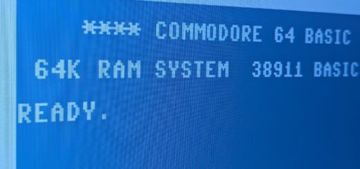
- Turn on your C-64 and observe the original Commodore 64 turn-on message. You should see: *** COMMODORE 64 BASIC V2 *** 64K RAM SYSTEM 38911 BASIC BYTES FREE READY
- Now Type:
- OPEN1,8,15,”Z8S” <RET>
- Reload the program from step 34 above. Time the load. It should be about 3 times slower than in step 34 above. By this time it probably getting very tedious to load at the slow speed.
- If you have trouble with one of the tests described above, carefully recheck the installation instructions starting at step 1.
- If you are still having trouble, replace your original Kernal ROM in the C-64 and the original Operating ROM in the 1541 Disk Drive. Test that this has returned the computer and disk drive to their original condition. Every 1541 FLASH! is tested before leaving the factory, but mistakes can happen.
- This completes the test of the 1541 FLASH!. Carefully replace the metal inner cover on the 1541 Disk Drive. The 2 small sheet metal screws are used to attach in on the left side.
- Unplug the power and serial cable from the 1541 disk drive.
- Replace the plastic top cover on the 1541 disk drive.
- Holding the two halves together turn the 1541 disk upside down.
- Insert the four screws into the the four corner wells on the bottom of the 1541.
- Turn the 1541 right side up and reinstall the power and serial cables. Turn on the 1541 disk drive.
- Turn off your C-64. Switch the small switch on the CableCard toward the C-64. Turn on your C-64.
- Reload the program from disk that you loaded in step 25 of the C-64 installation instructions. Time the load cycle. The program should load three times faster than previously.
- This completes the installation of the 1541 FLASH!. Please now read the section of the manual covering the “Easy Everyday Commands”.